WinKontrol 2007
- Content
- Introduction
- Necessary HW and operating system
- Instructions for experienced PC users
- Installation
- First start and WinKontrol Program setting
- Working with WinKontrol Program
- Data
- Report
- Chip
- Settings
- Information
- Licence, warranty
- WK Downloader
- ANTI-VANDAL®
- Working with sensors
- Uninstalling
- Technical parameters
- Quick course for basic work
Data
Menu Data is used in entering and setting individual sections of the PES ® Patrol Route System (sensors, chips, guards, shifts, etc.). Individual items will be described in detail later on.
The basic elements of the patrol system, such as sensors and control chips, must be entered in the program, so that reports can be generated. Without entering these fundamental parts, the program will not be able to create detailed reports or provide you with clear checks of your guards.
In all items in the Data section, you will find several similar control elements:
 |
New will create a new item.
An item is understood to mean, for example, a sensor, checkpoint or a guard. |
 |
Edit opens details selected from the list, so that these details can be edited. |
 |
Print list will print out a list of registered items in the currently open window. |
 |
Show development in changes, will show all changes that took place from entering the item in the program database. The following sample in recording changes in patrol route. 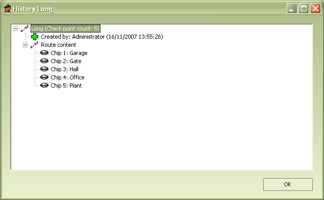 |
 |
Sorting items in directory in ascending order (for example, names from A to Z). |
 |
Sorting items in descending order, will sort items in reverse order. |
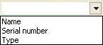 |
Sorting field determines the criteria according to which the items will be sorted.
The sorting option is available only in the Professional version. |
 |
Database status shows items from the maximum allowed number. |
 |
Report will print out report of selected item. |
The following is a description of individual sub-sections:
Sensor
Sensor section manages the list of your PES ® sensors. You can add them, delete them, edit them or print reports from them. The basic dialogue sensors’ window can be open by clicking on Sensor or relevant  icon.
icon.
You are looking at an actual list of your sensors, including serial numbers and type designations. 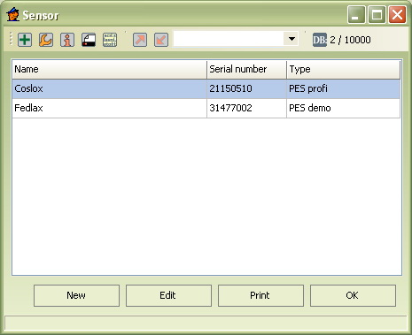
Entering a new sensor
- Click on New or icon.
- A dialogue window will open.
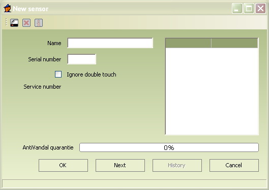
- On the line Label enter the designation you selected for the newly added sensor.
- In the column Serial number, enter the number, etched in the side of the new sensor. The program will automatically identify the type of the sensor entered.
- If you want the system to ignore the duplicate entry in case of repeated entry of the same chip again and again, check Ignore duplicate entry.
Example use: Example use: The guard did not hear the sound signal and missed the flash signal also and is not sure if the information was read. This is why he / she will attach the sensor to the checkpoint one more time.
- Confirm by clicking OK or by clicking on Next and continue to entering the next chip.
In the column Anti-Vandal ® warranty you will see percentage reminder of Anti-Vandal ® warranty; in case of a new sensor, the warranty is one hundred percent.
Editing saved sensor information
- In the Directory, double click on the chosen sensor, or highlight it and click on Edit or the appropriate icon.
- A dialogue window will open.
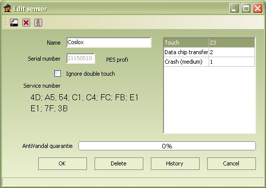
- Now, you can change the name, number and settings, or delete the sensor.
- Confirm by clicking OK.
In the left part of the dialogue window, you will see the service number of the relevant sensor. You will need this number in case you have to send the sensor for repairs. If you don’t report such number, any repair will take considerably a lot longer. Showing the service number may take several seconds.
The right hand side of the dialogue window will show status of the relevant sensor – number of touch contacts data transfers and Anti-Vandal ® information. Number of touch-contacts expresses how many touch-contacts there were between the scanner and identification chip. Data transfer through data chip represents the number of data transfers into the data chip. Data transfer through TMD adapter means a number of data transferred directly into the computer through the TMD adapter. Another Anti-Vandal ® system information shows how many impacts, short circuits, power surges, extreme temperatures or microwaves was the system exposed to.
The percentage indicator shows your remaining Anti-Vandal ® warranty.
Showing all Anti-Vandal ® events may take a while, depending on the size of your database.
The Guard
In the guard section of the program, you enter your guards and their assigned identification chips. Usually, each guard has his / her own unique chip, he / she will touch-contact the sensor with before each patrol route. The report then makes it easy to identify, which guard had actually covered the assigned patrol route.
Open the basic dialogue window by clicking on Guard or the relevant  icon. The list will show all registered guards and their identification chip numbers.
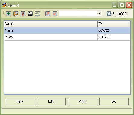
Entering a new guard
- Click on New or the relevant icon. A dialogue window will appear.
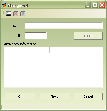
- In the field Nameenter the guard’s name.
- Click in the empty field IDor the Touch-contactbutton and touch-contact the new patrol officer’s identification chip to the adapter.
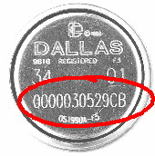
- Or, copy the last 6 character (letters and numbers) of the code from the chip that has been assigned to the new guard. PICTURE!
- Confirm by clicking OKor by clicking on Nextand enter the next guard.
Editing guard’s data
- In the directory, double-click on guard’s name, whose data you wish to change, or highlight the name and click on Editor the .
- A dialogue window will open.
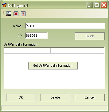
- In the details shown, you may delete the guard, change his / her name or change the chip number assigned.
- Confirm by clicking OK.
After clicking on Get Anti-Vandal ® information , you will see the number of attempts by the guard to damage / destroy the sensor.
Showing all Anti-Vandal ® events may take a while, depending on the size of your database.
Checkpoint
Individual numbers and description of control chips are stored in the Checkpoint section. These chips are situated in places, that the guard must check on his / her patrol route. The basic dialogue window is opened by clicking on Checkpointor a related  .
.
The list shows all registered chips: their labels and numbers. 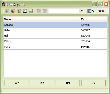
Entering a new checkpoint
- Click on New or icon.
- A dialogue window will open.
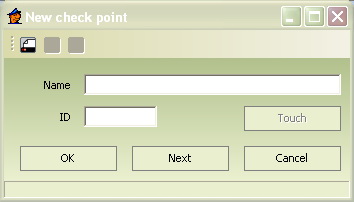
- Enter the name of new checkpoint.
For easier orientation in reports, we recommend entering names of individual chips that are descriptive and appropriately fitting. For example: hall, garage, gate…
- Click in the empty field ID or the Touch-contact button and touch-contact the given identification chip to the adapter.
- Or, copy the last 6 characters (numbers and letter) of the code, etched on the control chip.
- Confirm by clicking OKor by clicking on Nextand continue in entering the next chip.
Editing saved checkpoint data; deleting saved checkpoint
- In the Checkpoints directory, double click on the selected checkpoint or highlight it and click on Edit or the icon.
- A dialogue window will open.

- You can change saved details of a given chip in the details shown (label, number).
- Clicking on Delete, will remove the checkpoint from the database.
- Confirm by clicking OK.
Route
In the section Patrol Route, you enter the sequence of checkpoints that have to be downloaded by the guards. This outlines the guards' patrol route. Another criteria may be established for evaluation rating of given patrol routes. The principal advantage is creating a system with simplified controls. The report will then show brief information about the patrol route and if the route was taken and by which guard.
The routes should be easily remembered by the guards.
To the less experienced users we recommend they take care at the beginning that start of each patrol route begins with downloading the guard’s chip. Especially in cases when numerous routes are downloaded in sequence Downloading the guard’s chip will start a new patrol route, which separates it from all other routes.
Note for experienced users: Individual routes may be separated by data transfer to data chip. The route is ended by one of two following events:
- The guard’s chip
- Transfer data to the data chip.
Basic dialogue window opens once you click on Route or the relevant  icon. You now have before you the current list of your patrol routes.
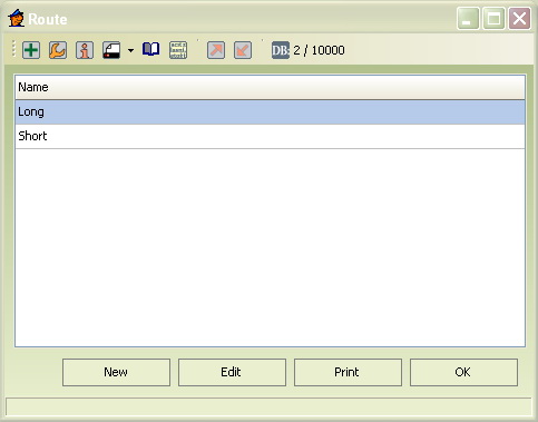
Creating new patrol route
- Click on New or icon.
- A dialogue window will open
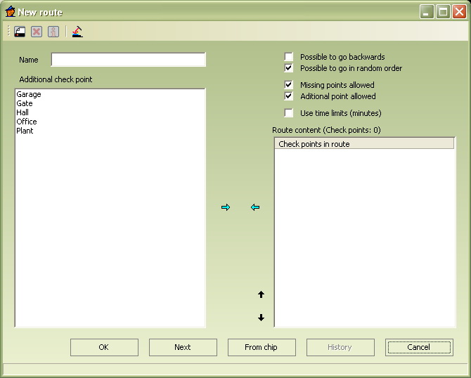
- Select the name of new patrol route.
- In the left hand part of the window, you will see the latest list of checkpoints that are entered in the program.
- Highlight with your mouse the first checkpoint of the new route and click on the
 . The checkpoint will be copied into the route.
 - Similarly, select all points you wish to enter into the patrol route.
- Remove checkpoints with
 .
. - Sequence of checkpoints in the route may be changed by
 and
and  .
. - Checking individual choices in the upper right hand part of the window, you may select other characteristics:
- Checking May be covered in reverse direction you will enable the route to be taken even in the reverse direction. This program setting will recognize the route, even if chips are downloaded in in reverse order. The program will add In Reverse Order to the patrol route report.
- Checking May be covered randomly you will enable reading the route in random order. The system will still recognize the route. . Information form all chips must be downloaded, unless determined otherwise.
- By checking Patrol route may be missing checkpoints ,you will enable the system to recognize the route, even though some checkpoints are missing. The program will notify you of all missing checkpoints
In evaluating a patrol routes with missing checkpoints, such patrol routes are disadvantagedcompared with other, complete routes.
Single patrol route may not be missing more than 2, or rather 10% points (this setting may be changed). If there are more points missing, the program will not be able to identify this route. . A route report with missing points will then advise that Checkpoints do not match with patrol route selected.
- Checking selection Patrol route may have extra checkpoints will enable you to download in other checkpoints that do not belong to the given patrol route, but the program will still recognize this route. The program will notify of these extra checkpoints in the report.
In evaluating a patrol routes with extra checkpoints, such patrol routes are disadvantaged, compared with other, correctly downloaded routes.
- Checking the selection Use time limit and setting certain values (in minutes) you set minimum time that has to pass between downloading two, next following checkpoints.
- Confirm finished route by clicking OK or by clicking on Next and continue to entering the next route.
Creating new patrol route by reading from chip
Reading from chips in appropriate sequence and downloading this sequence from the scanner to PC, is another way how to enter the patrol route into the program.
- Through the scanner, download checkpoints in such sequence, as it should appear in the route.
- Copy the data by touch-contact with the data chip (or directly into the computer).
- If you need to create another patrol route, download its checkpoints the same way and again, transfer the information into the data chip.
- In the dialogue window New patrol route, click on the From chip button and after you are asked to, touch-contact the chip to the adapter.
- If you’d transferred more than one route, the following dialogue window will open.
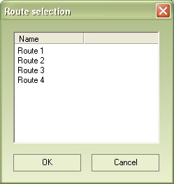
The downloaded new patrol routes remain in the data chip and are not deleted. Saving new patrol routes will necessitate creating a new transfer chip.
- Highlight the patrol route you wish to save first and click on OK.
- Select the name of new patrol route.
- The right-hand side will now show the sequence of checkpoints along the patrol route. The patrol route may be adapted to suit your needs and define its other characteristics.
- Confirm by clicking OK.
- If you wish to create another patrol route saved on the data chip, repeat the above.
List of control chips and their serial numbers
List of control chips and their serial numbers, in case of a specific route, can be shown by highlighting a given patrol route in the list and clicking on the  icon.
icon. 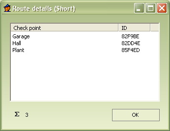
Editing data of saved patrol route, deleting patrol route
- In the routes directory, double clicking on the selected route will open it or highlight it and click on Edit or the icon.
- The route setting will open.
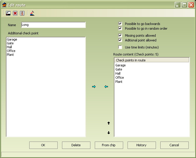
- In the details shown, you can edit the information entered.
- Add or delete checkpoints in the patrol route or change their sequence.
- You may change other settings: permitting extra checkpoints / missing checkpoints, pre-set time limit… similarly as in creating a new patrol route.
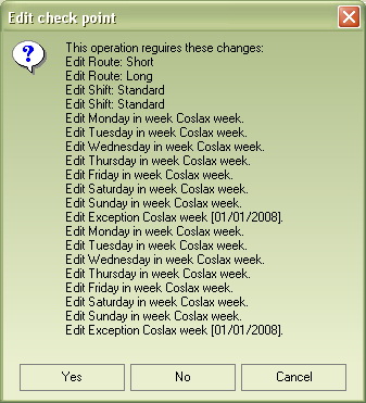
The program may notify you that changes will be applied in the other settings, (for example shifts and a given week).
- Clicking on Delete, will remove the route from the database.
- Confirm by clicking OK.
Shift
In this section, you may create shifts from all registered sensors and patrol routes. The shifts system makes controls of guards easier. In each shift, you set a plan of individual patrol routes, when they should start and when they should end. This then gives a clear schedule of patrol routes that the guard must meet. Shift may be a maximum 24 hours, which means that it represents patrol routes of one whole day.
In creating shifts, patrol routes must be entered in the program.
The basic dialogue window is open by clicking on Shiftof the appropriate  icon. You now have before you an up to date list of all shifts created and all the assigned sensors.
 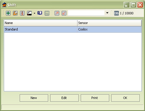 .
.
Creating a new shift
- Click on New or icon.
- A dialogue window will open
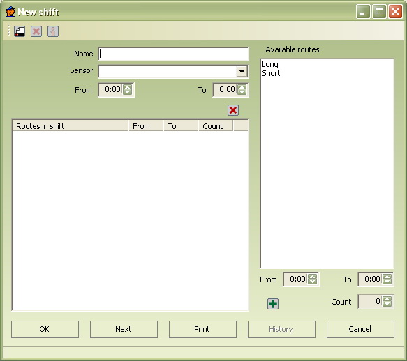
- Enter the name of new shift.
We recommend you use descriptive names, as it relates to the work schedule of your guards. Therefore, for example, according to the weekday, shift type – day / night, etc.
- In the next field, select the sensor you wish to assign the new shift.
- In the Shift selection, enter times of the new shift, e.g. between what hours.
Length of one shift may be entered in the range of 00:00 - 23:59. This is only a time interval; the shift may continue throughout the night (22:00 - 10:00).
- In the left-hand side, you see a list of the actual routes: click on the route, you wish to place in the shift. In the fields From and To, set the time span, when the patrol route should be taken.
- In the fields From and To, define a time period, when the patrol route should be taken.
Times of individual patrol routes in a given shift may not overlap. There must be a minimum of 1 minute between individual patrol routes. For example, if Patrol Route 1 runs until 9:30, Patrol Route 2 may begin at 9:31 at the earliest.
In shift settings, time interval of 8:30 – 9:30 in fact means 8:30:00 – 9:30:59.
- Copy the patrol route into the new shift through the button.
- You can delete a route at anytime by highlighting it and clicking on
 .
. - Confirm by clicking OK.
Editing information of saved shift, deleting shift.
In the Shift directory, double click on the selected shift or highlight it and click on Edit or the Icon. Each shift’s name may be changed, have patrol routes added or deleted, change their sequence, change assigned sensors, as well as time schedules of individual patrol routes and the whole shift. 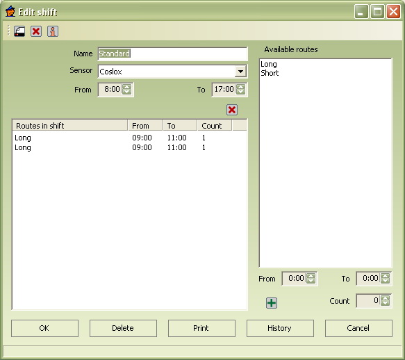
Shift details
Highlighting a specific patrol route and clicking on Details or an icon, you will see detailed information about the patrol route selected. 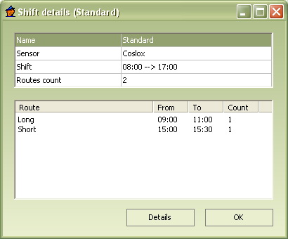
Week
Selection Week, enables you to assign saved shift to individual weekdays, which gives you a clear overview of shifts for the whole week.
In creating shifts, patrol routes must be entered in the program.
The basic dialogue Weeks window can be open by clicking on Weekor relevant  icon.
icon. 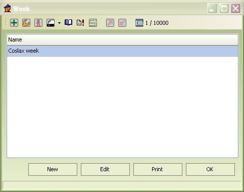
Creating a new Week
- Click on New or icon.
- A dialogue window will open
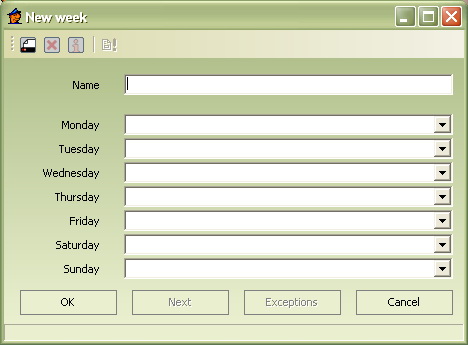
- Enter the name of week created.
For example, by the month or year, when this schedule applies.
- With the arrows on right hand side of each day of the week, assign the appropriate shifts.
- Confirm by clicking OK.
Since normal time schedule may be impacted on by statutory holidays or company holidays, the WinKontrol program also offers Exceptions in the Weeksettings.
Pre-setting exceptions
- This selection is accessible by clicking on Exceptions in window of the selected specific week or highlighting a given week and clicking on icon
 .
. - Exceptions dialogue window will open.
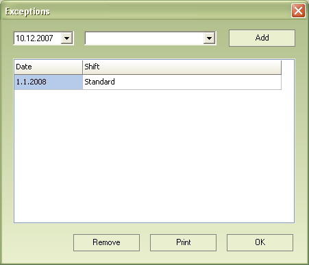
- In the first column, select the date, where the exception will apply.
- In the next column, select the applicable shift on that day (regardless to the settings of the week).
- Confirm by clicking OK.
We recommend creating a special shift just for statutory holidays and other usual cases, which can then be used simply in pre-setting Exceptions.
Editing information of saved week, deleting week.
In the directory Week of the dialogue window, double click on the selected week or highlight it and click on Editor the icon. In every Week, you can change name, add and delete shifts, change their sequence, change assigned sensors, as well as the time schedules of individual patrol routes, as well as the entire shift. 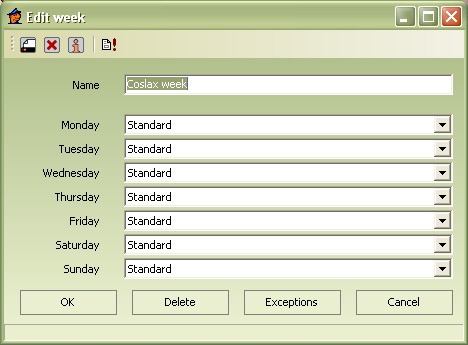
Keypad
In this section, you can enter your Keypads into the program. These special sets of twelve chips, arranged as simple keypads, make it possible to record exceptional events with the help of numeric codes (Working with keypads).
If you are using the TOMST ® Keypad together with the sensor, whose number (etched on the side) begins with the number 3, you don’t have to enter the keypad information into the program. These sensors are automatically able to work with the TOMST ® Keypad.
The basic dialogue Keypad’ window can be open by clicking on Keypador relevant  icon. You now have before you the current list of your saved keypads.
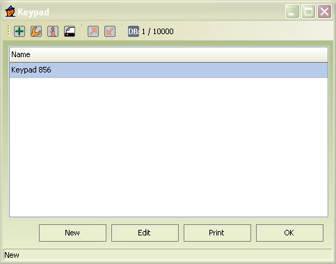
Entering new keypad
- Click on New or icon.
- A dialogue window will open
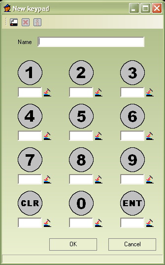
- Select name of new keypad.
- In chip description, click on the empty field or an
 icon and after you are asked, touch-contact the new keypad chip to the adapter. The system will download the chip number and will save it.
 - Or, numbers may be entered manually. In that case, copy the last 6 characters (numbers and letter) of the code, etched on the control chip.
- You can interrupt the chip registration by pressing the Esc key.
- Similarly, you can download, or copy all new keypad chips.
- Confirm by clicking OK.
Events
In the section Events, you may create a list of possible non-standard situations, the guards must record on their patrol routes. . For example, an unlocked office, open window, fire, etc. The program will identify the recorded event in the printed out report and will name it (more in instructions to use keypads and chips for recording events).
Basic dialogue window opens once you click on Events or the  icon. You now have before you an updated list of all events and their relevant codes.
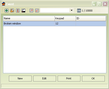
Entering a new event
- Click on New or icon.
- A dialogue window will open
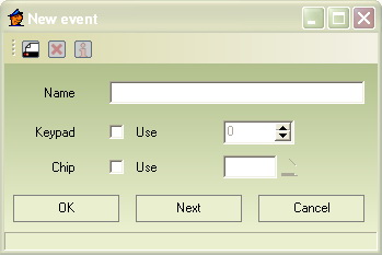
- Enter the type of event.
The event type should be descriptive, therefore for example: fire, open window, lights left on, gates unlocked, etc.
- Select, if you want to record this event through a keypad or with chip you choose. You may use both methods (the guard will use the one, he / she has at his / her disposal).
- If you select Keypad, enter the appropriate numeric code, corresponding with the event.
For example, if open window has code 12, then upon discovery, the guard will take the assigned keypad, touch-contacts to chip 1, then chip 2, and finally to chip E (Enter).
- If you opt for Chip click in the chip’s empty field or the icon and after you are asked, touch-contact the chip with the adapter.
- Or, numbers may be entered manually. In that case, copy the last 6 characters (numbers and letter) of the code, etched on the control chip.
If, for example, the event open window has an assigned chip, then in case the guard discovers an open window, he will touch-contact the chip to the sensor.
- Confirm by clicking on OK, or go to entering another event by clicking on Next.
Gates
This selection will allow you to enter a list of new gates into the program – part of attendance system. Basic dialogue window opens once you click on Gates or the  icon.
icon. 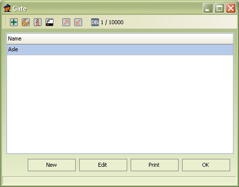
Entering new gates
- Click on New or icon.
- A dialogue window will open
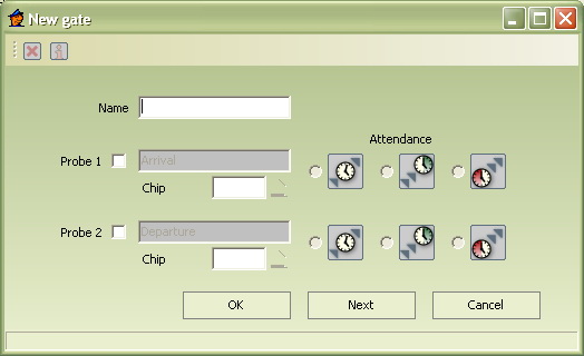
- Enter the name of the gate.
- Checking fields Probe 1 and Probe 2, will activate these selections. You may have one or two probes at the gate.
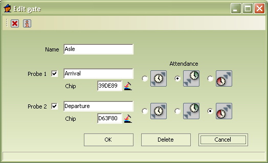
- In checking one probe (or both probes), you now have to record the relevant chips.
- Click on the icon and then, touch-contact the correct chip with the adapter. The system will download the chip number and save it.
- Or, numbers may be entered manually. In that case, copy the last 6 characters (numbers and letter) of the code, etched on the control chip.
- Now, select a probe(s) with options listed on the right. You may select that the given probe:
- Has
 on attendance
 - Represents

- Represents

- Has
- Save the created gate by clicking OK or click on Next, if you want to create another gate.
| Up | Next |
|---|